As my usage of OpenShift Virtualization increases, I am finding that I need to create a dedicated network for my storage arrays. For my lab storage I use two Synology devices, both are configured with NFS and iSCSI, and I use these storage types interchangeably. However in the current configuration, all storage traffic (NFS or iSCSI) is routed over two hops, and comes into the server over a 1Gb interface. I would like to change this to work similar to my vSphere lab setup, where all storage traffic goes over my dedicated network “vlan20”, which is not routed, and has a dedicated 10Gb switch.
In order to do this, I am going to make use of the NMState operator, and configure one of my 10Gb interfaces to be on vlan20. NMState is a declarative node network configuration driven through Kubernetes API. This means that we can create multiple forms of Linux network devices (bridges, interfaces, bonds, vlans, etc), assign IP addresses and configure things like MTU.
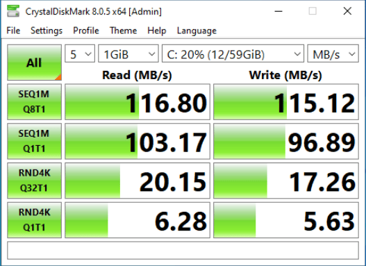
Why go through this effort? Here is a quick Crystal Disk Mark run using the default network interface:
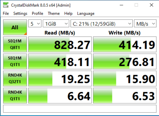
And here is the same disk benchmark run over the dedicated 10Gb network
Now, while I am creating this secondary network interface on my server to grant access to my storage arrays, NMState can be used for more than just the creation of a storage network. I will be going into other uses in upcoming blog posts.
I have covered this topic once before: NMState Operator and OpenShift Container Platform, but I wanted to update this process since NMState is now a fully GA feature. We will also be using static IP addressing to show how to configure static IP addresses and change the MTU for the interface.
NOTE: One thing NMState can not do is modify your PRIMARY interface on your OpenShift nodes. The interface that is configured as your primary interface is a fixed item and can not be modified at this time.
Prerequisites
You will need an OpenShift cluster that is already configured and deployed. You will also need to have multiple network cards available in your cluster. In this blog post we will be using an Intel X710 card, however you can use any spare network interface you may have on your server.
WARNING: Be aware that when you connect additional network interfaces to your OpenShift cluster, if DHCP is available on the default VLAN for that connection, OpenShift WILL configure an IP address on that interface. This can quickly become an issue if you have multiple subnets with default routes, as OpenShift will not know which one to use as primary.
Installing the NMState Operator
The NMState Operator is the easiest way to get NMState installed in your cluster. We will navigate to OperatorHub in the OpenShift UI and follow the steps below to install the operator:
- Log in to the OpenShift Console
- Select Operators -> OperatorHub
- Search “NMState” operator
- Select NMState Operator
- Click Install
- Use the Operator recommended Namespace option “openshift-nmstate”
- Accept all defaults, click Install
Once Operator is installed, select “View Operator” and ensure that the Status shows Succeeded before proceeding.
Finding network interfaces
With multiple network cards installed on a node, finding the proper ethernet interface name can be tricky. I have found that using a mixture of ip link show and ethtool can usually help you to identify the proper interface you are looking to configure. In the example case, I am looking to configure the interface with MAC Address 14:02:ec:7e:02:70 as identified from my network switch. Using the ip link show command I can see that this interface is known as eno49.
$ ip link show
1: lo: <LOOPBACK,UP,LOWER_UP> mtu 65536 qdisc noqueue state UNKNOWN mode DEFAULT group default qlen 1000
    link/loopback 00:00:00:00:00:00 brd 00:00:00:00:00:00
2: eno1: <BROADCAST,MULTICAST,UP,LOWER_UP> mtu 1500 qdisc mq master ovs-system state UP mode DEFAULT group default qlen 1000
    link/ether ec:eb:b8:97:af:ac brd ff:ff:ff:ff:ff:ff
    altname enp2s0f0
3: eno2: <NO-CARRIER,BROADCAST,MULTICAST,UP> mtu 1500 qdisc mq state DOWN mode DEFAULT group default qlen 1000
    link/ether ec:eb:b8:97:af:ad brd ff:ff:ff:ff:ff:ff
    altname enp2s0f1
4: eno49: <BROADCAST,MULTICAST,UP,LOWER_UP> mtu 1500 qdisc mq state UP mode DEFAULT group default qlen 1000
    link/ether 14:02:ec:7e:02:70 brd ff:ff:ff:ff:ff:ff
    altname enp4s0f0
Creating our NNCP and apply to your cluster
With the network interface identified, and the NMState Operator installed in our cluster, it is time to create our NodeNetworkConfigurationPolicy (NNCP). Since we will be assigning static IP addresses to this interface, we need to properly identify which host the NNCP will apply to. Use the oc get nodes command to get a list of the node host names. In the example below there is only one node in the cluster.
$ oc get nodes
NAME                STATUS   ROLES                                   AGE    VERSION
ec-eb-b8-97-af-ac   Ready    control-plane,master,master-hp,worker   244d   v1.28.7+f1b5f6c
We will be assigning an IP address of 172.16.20.20 to this node with a netmask of 255.255.255.0. We will target the proper node by using a nodeSelector that selects based on the kubernetes.io/hostname node label. In addition we will set the MTU to 9000 to enable the transmission of larger TCP blocks:
apiVersion: nmstate.io/v1
kind: NodeNetworkConfigurationPolicy
metadata:
  name: storage-network-config
spec:
  nodeSelector:
    kubernetes.io/hostname: ec-eb-b8-97-af-ac
  desiredState:
    interfaces:
    - name: eno49
      type: ethernet
      state: up
      mtu: 9000
      ipv4:
        address:
        - ip: 172.16.20.20
          prefix-length: 24
        dhcp: false
        enabled: true
If you have multiple nodes in your cluster, and you are configuring static IP addresses for each node, you will have an NNCP for each node in your cluster.
Applying your Configuration
We can now apply the NodeNetworkConfigurationPolicy we created in the last step to the cluster. Use the oc command to apply the yaml to your cluster
$ oc create -f storage-network-config.yml
nodenetworkconfigurationpolicy.nmstate.io/storage-network-config created
The NMState Operator will now take over and apply the configuration to your cluster. To check on the state of the changes we will check the NodeNetworkConfigurationEnactment (NNCE) by using the oc get nnce command:
$ oc get nnce
NAME                STATUS
ec-eb-b8-97-af-ac   SuccessfullyConfigured
When all nodes show as “Successfully Configured” you can move on to the next steps.
Validating your New Settings
We can now check to ensure that the settings were properly applied at the node level, and test end-to-end connectivity with a JumboFrames ping.
Start by connecting to the node we used in the previous section and running the ip a command
$ oc debug node/ec-eb-b8-97-af-ac
$ chroot /host
# ip a
1: lo: <LOOPBACK,UP,LOWER_UP> mtu 65536 qdisc noqueue state UNKNOWN group default qlen 1000
    link/loopback 00:00:00:00:00:00 brd 00:00:00:00:00:00
    inet 127.0.0.1/8 scope host lo
       valid_lft forever preferred_lft forever
    inet6 ::1/128 scope host
       valid_lft forever preferred_lft forever
6: eno49: <BROADCAST,MULTICAST,UP,LOWER_UP> mtu 9000 qdisc mq state UP group default qlen 1000
    link/ether 14:02:ec:7e:02:70 brd ff:ff:ff:ff:ff:ff
    altname enp4s0f0
    inet 172.16.20.20/24 brd 172.16.20.255 scope global noprefixroute eno49
       valid_lft forever preferred_lft forever
    inet6 fe80::b4d8:d18f:cd8c:15a3/64 scope link noprefixroute
       valid_lft forever preferred_lft forever
Looking at the configuration for eno49 we can see that we have successfully configured the IP address on the interface, and the MTU has been properly set to 9000.
We can conduct an “end-to-end” test validating that our JumboFrames setting is working at the networking layer by pinging your storage array. You will need to know the IP address of your storage array before running the next step. In the example command, our storage array is using IP address 172.16.20.10
# ping -M do -s 8972 -c 5 172.16.20.10
PING 172.16.20.10 (172.16.20.10) 8972(9000) bytes of data.
8980 bytes from 172.16.20.10: icmp_seq=1 ttl=64 time=0.569 ms
8980 bytes from 172.16.20.10: icmp_seq=2 ttl=64 time=0.587 ms
8980 bytes from 172.16.20.10: icmp_seq=3 ttl=64 time=0.804 ms
8980 bytes from 172.16.20.10: icmp_seq=4 ttl=64 time=0.641 ms
8980 bytes from 172.16.20.10: icmp_seq=5 ttl=64 time=0.717 ms

--- 172.16.20.10 ping statistics ---
5 packets transmitted, 5 received, 0% packet loss, time 4091ms
rtt min/avg/max/mdev = 0.569/0.663/0.804/0.091 ms
Assuming your ping command is successful congratulations, your network interface is now properly configured for Jumbo Frames. If you are seeing errors, jump to the next section.
Troubleshooting Network errors
You may get one of two errors when testing the ping command. If you get an error stating ping: local error: Message too long, mtu=9000 check the settings on your node again, this error indicates that the machine’s MTU is not configured correctly.
The other error that can happen is packet loss and ping failure which will look like this:
# ping -M do -s 8972 -c 5 172.16.20.10
PING 172.16.20.10 (172.16.20.10) 8172(8200) bytes of data.
--- 172.16.20.10 ping statistics ---
5 packets transmitted, 0 received, 100% packet loss, time 4116ms
This indicates that the physical network layer is not properly configured for ethernet packets that are 9000 bytes in size. Check your networking equipment, or contact your friendly network administrator to see if they can help fix the issue.
Conclusion
With your storage network properly configured, you can now configure your CSI storage drivers to connect to your storage array over this dedicated network. The exact steps to do this will vary depending on your CSI driver and storage hardware. This article discusses just one of many options for how to configure an ethernet interface on a dedicated storage network. Be sure to check Observing and updating the node network state and configuration and review other options that are possible with the Kubernetes NMState Operator.

